


Introduction
The purpose of this article is to delve deeper into the topic of hydraulic motors, their operation, the different types that exist as well as their main advantages and disadvantages.
Table of Contents
- What is a hydraulic motor?
- Symbol of the hydraulic motor in hydraulic circuits.
- What is a hydraulic motor used for?
- Operation of the hydraulic motor.
- How to choose a hydraulic motor?
- Types of hydraulic motors.
- Orbital hydraulic motors.
- External gear hydraulic motors.
- Vane hydraulic motors.
- Piston hydraulic motors.
- Final drives.
What is a hydraulic motor?
Unlike the hydraulic pump, the hydraulic motor is a mechanical component that converts hydraulic energy (flow and pressure) into mechanical rotational energy (torque and speed). It is the hydraulic actuator responsible for generating torque at a certain rotation speed.
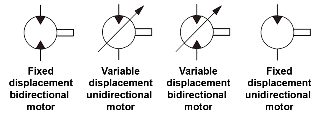
Symbol of the hydraulic motor in hydraulic circuits.
What is a hydraulic motor used for?
It is the hydraulic component that provides torque at a certain rotation speed. They can be used to replace manual work or in places where an electric motor is not viable due to lack of available electric power or because they are wet work areas.
They are used in a multitude of different applications: winches, lawnmowers, brush cutters, mixers, drilling machines, agitators, hydraulic hammers, plastic injection machinery, and many more agricultural, industrial, nautical, fishing applications, etc.
Operation of the hydraulic motor.
For a hydraulic motor to function, it must receive a flow of hydraulic fluid that pushes against the gears, pistons, or vanes of the motor to make the motor's output shaft move. Under such conditions, the motor shaft will rotate and generate torque.
The torque generated by the motor will depend on the motor's displacement and the pressure drop in the motor. The larger the displacement, the more torque. The greater the pressure drop in the motor (with the same displacement), the greater the rotational torque generated.
The speed of the motor will depend on the flow and displacement of the motor. The greater the flow, the higher the speed. The larger the displacement (with the same flow), the lower the speed.
IMPORTANT!
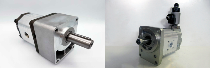
A hydraulic motor must be protected both mechanically (bearings, elastic coupling, etc.) and hydraulically (pressure relief valves, anti-cavitation valves, shock valves, flow limiters, etc).
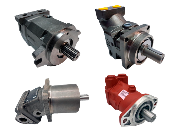
In the following image, you can see 2 hydraulic motors protected with bearing support and Venting electric valve respectively.
How to choose a hydraulic motor?
The selection of the hydraulic motor will depend on a series of crucially important variables:
- Torque required by the application.
- Rotation speed requested by the machine.
- Radial / axial stresses that will be on the motor shaft.
- Flow and pressure available.
Based on all these basic variables, the required motor displacement and the type of motor will be calculated. Once the motor model is chosen, it must be verified that the oil flow that will reach the motor and the available pressure will be sufficient to obtain the necessary rotation speed and torque.
Types of hydraulic motors.
Hydraulic motors can be classified based on their constructional characteristics:
- Orbital hydraulic motors.
- External gear hydraulic motors.
- Hydraulic motors with internal gears.
- Piston hydraulic motors (axial or radial).
Orbital hydraulic motors.
Orbital type hydraulic motors are characterized by being fixed displacement and having a design prepared to provide a high torque. For a given motor displacement, its rotation speed will be determined, among other variables, by the flow of hydraulic oil that reaches the motor. The greater the flow, the faster the shaft of the hydraulic motor will rotate.
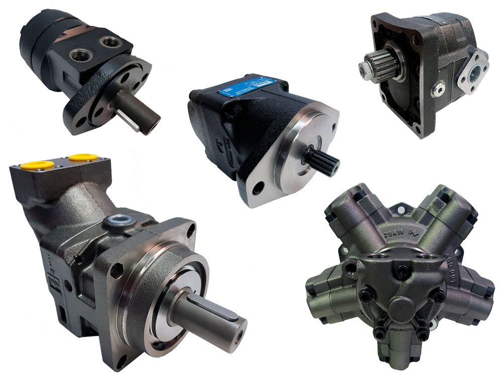
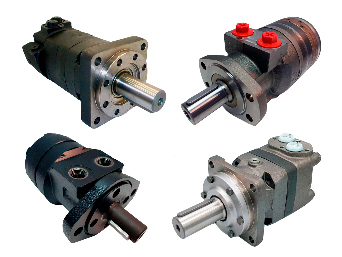
Image of orbital hydraulic motors. They are used in all types of mobile and industrial machinery.
The constructive design of orbital motors is based on the type of internal gears. It consists of a pair of gears where there is a fixed external gear and the rotating gear is the internal one (also called "star" or "orbitrol") that rotates inside the fixed gear.
Regarding the design of the external (fixed) gear, there are basically 2 types:
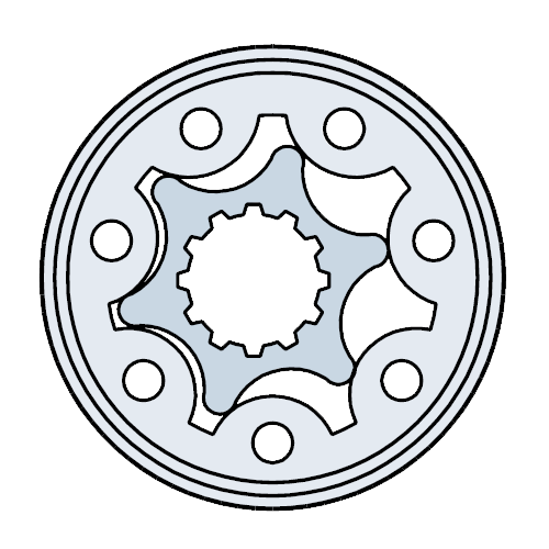
- "Gerotor" type: the gear is flat. See image:
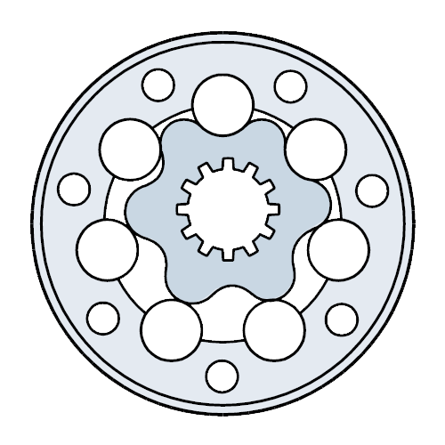
- "Geroller" type: the gear has rollers. See the following image:
In Sauer Danfoss (now White for the small motor range and Danfoss for the larger motor range), the gerotor type motor is in its OML, OMM, OMP (OMPX), and DH ranges.
In Sauer Danfoss, the geroller type motor is in its OMR (OMRX), DS, OMH, OMEW, OMS, OMT, OMV, and TMT ranges.
To cover all market needs, there are numerous variants and options in this type of motors:
- Motors with parts resistant to corrosion (for, for example, applications near the sea).
- Motors with dust seal on their shaft (sweepers).
- Wheel type motors.
- Motors with needle bearing (applications where there are starts/stops with high frequency, existence of vibrations in the shaft, high static radial load, etc.
- Special version for very low internal leaks.
- Short motor type version special for gears or reducers that already have their bearings to absorb axial and radial forces.
- Motors with integrated brake.
- Motors with tachometer.
- Motors with built-in speed sensor.
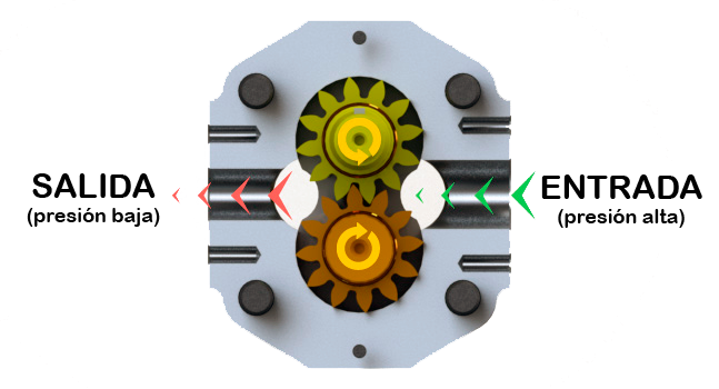
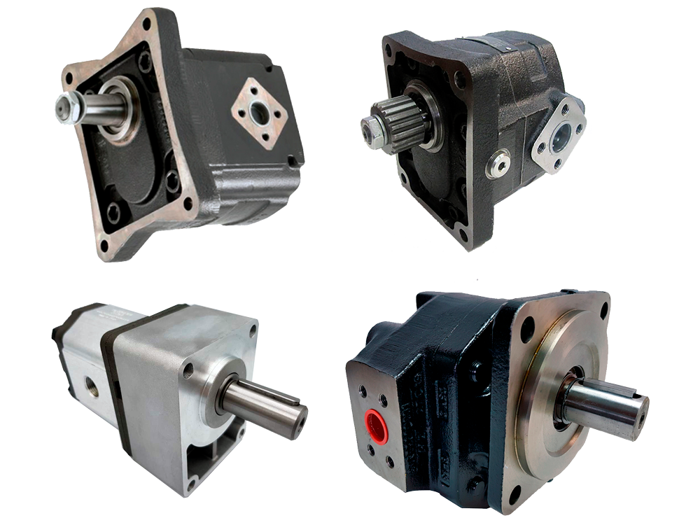
External gear hydraulic motors.
The design of hydraulic motors with external gears consists of 2 identical straight (or helical) gears that rotate interconnected inside a body.
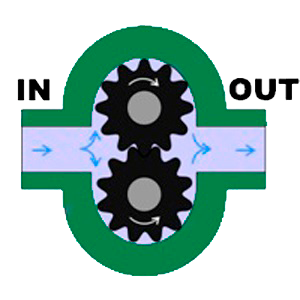
They are also called pinion or gear hydraulic motors. This type of hydraulic component, due to its compact design, robustness, and economical price, is used in all types of hydraulic machinery.
The range of options within this type of motors is very wide:
- Gear motors with aluminum body or iron/steel (cast) body.
- Unidirectional hydraulic motors (left or right rotation looking at the shaft) or reversible/bidirectional motors (available with internal or posterior, lateral, or frontal external drainage) that can rotate their shaft in both directions.
- Multiple types of shaft (conical, splined, cylindrical, etc.).
- Available with all types of front mounts: European flange (Italian flange), SAE-A flange, SAE-AA flange, SAE-B flange, SAE-C flange, Bosch type, etc.
- Hydraulic connections to the motor by BSPP (GAS) thread, UNF-SAE thread, for Dowty type flange, SAE type flange, etc.
- Depending on the compatibility of the hydraulic fluid to be used in the system or the maximum/minimum working temperature, the pinion hydraulic motor can also be configured according to the type of material in internal seals and in the shaft seal: NBR, FKM, Viton, etc.
- Valves integrated into the motor: the motor can be configured with or without integrated pressure relief valve, with anti-cavitation valve, with LS Load Sensing valve, with electric by-pass valve, with flow regulator valve, etc.
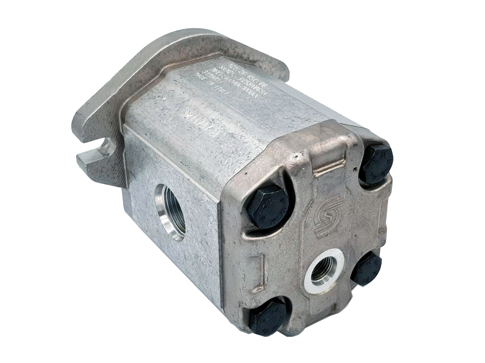
External gear hydraulic motors and aluminum body.
Depending on the displacement and size of the motor, they are divided according to the following nomenclature:
- Group 0.
- Group 1.
- Group 2.
- Group 3.
- Group 3.5.
- Group 4.
External gear hydraulic motors and cast iron body.
They are used in situations where aluminum motors are at the limit of their design either due to the type of application, the work cycle, or the harsh conditions demanded during the cycle.
Like motors with an aluminum body, those with a cast iron body are available in numerous configurations and sizes according to their displacement, their type of drive shaft, fixings and ports, integrated valves, Buna or Viton seals, internal/external drainage, etc.
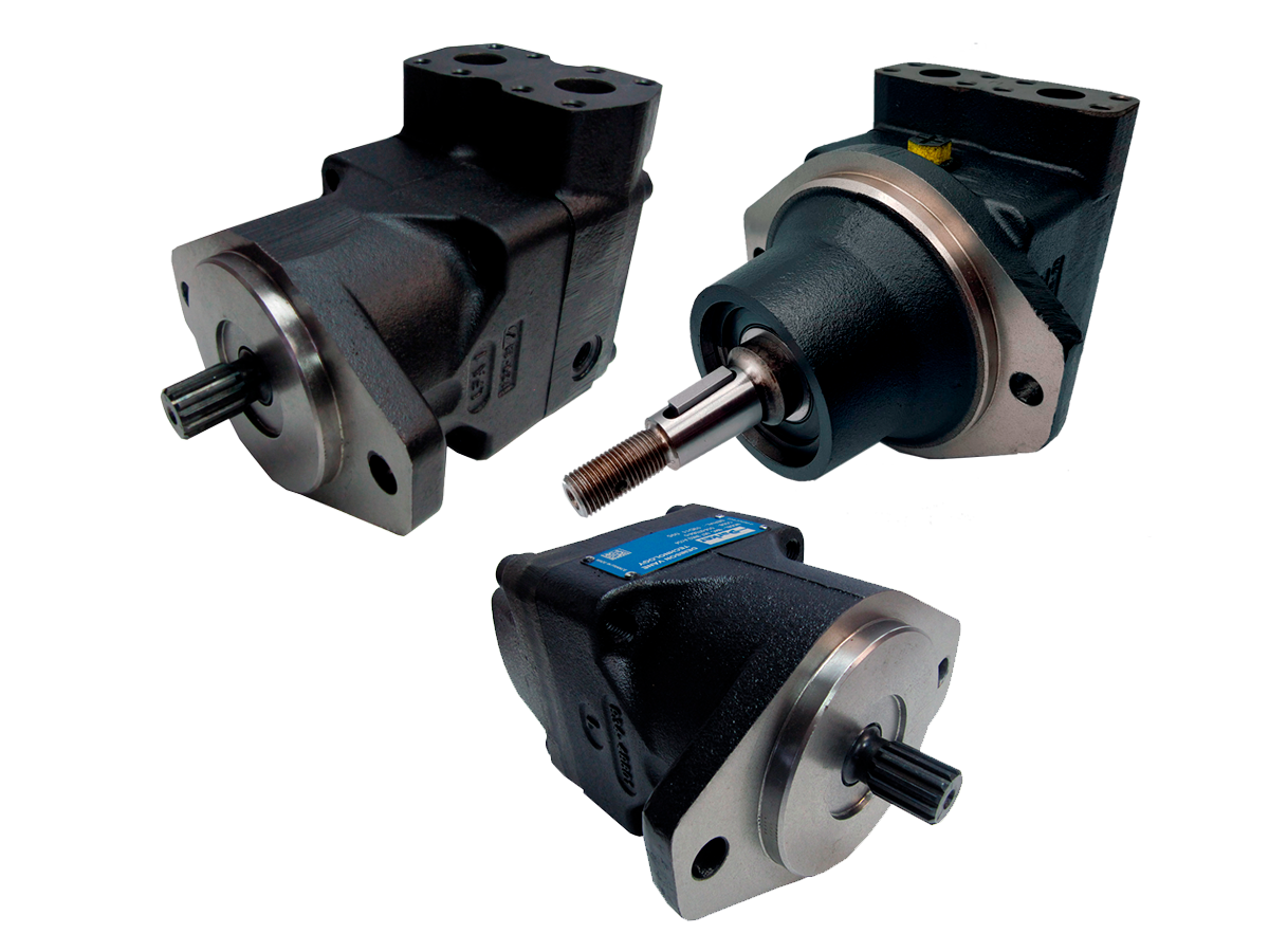
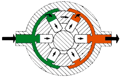
Hydraulic vane motors.
Hydraulic vane motors consist of a rotor containing vanes, which rotates within a cycloidal-shaped cavity. In most models of hydraulic vane motors, the inlet/outlet chambers are diametrically opposed, so the rotor is hydraulically balanced. This way, the bearings do not suffer excessively from hydraulic loads and allow a long duration.
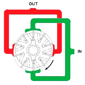
Image of hydraulic vane motors. They are used in agricultural machinery and in mobile or industrial machinery.
Hydraulic piston motors.
Depending on the configuration and design, hydraulic piston motors can be divided into 2 types:
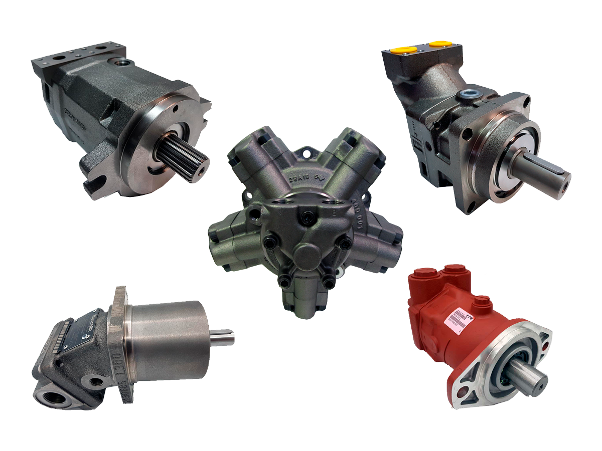
They can also be divided into motors with fixed or variable displacement.
Axial piston hydraulic motors.
They are generally composed of a certain number of cylinders that move a certain stroke in a reciprocal manner within a cylinder block (also called a barrel). Depending on the inclination of the plate containing the piston heads, the displacement will be greater or lesser. If the inclination is at an angle of 0 degrees, the stroke the pistons move will also be 0, therefore the flow will be equal to 0.
In constant displacement piston motors, this inclination is already defined at a certain angle that cannot be varied. However, in motors with a variable flow system, this inclination can be varied depending on the type of control or command that the pump contains.
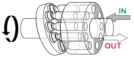
Axial piston hydraulic motors are characterized by their robustness and resistance and by a wide range of options available for their displacement control. Therefore, they are used in medium/high pressure applications that require a demanding and controlled work cycle, both for mobile machinery and for industrial hydraulic applications.
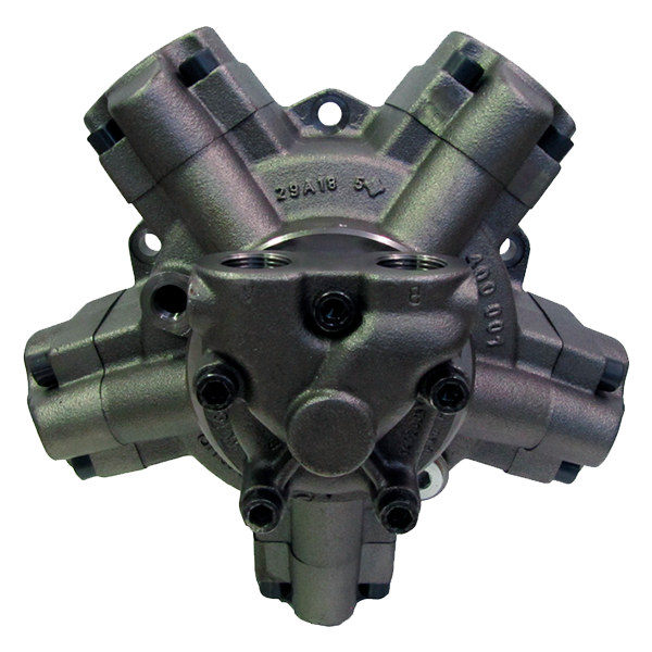
Radial piston hydraulic motors.
Radial piston motors have pistons placed symmetrically around the axis in a radial direction, and each piston moves reciprocally within its corresponding cylinder.
Radial piston hydraulic motors are available in both fixed and variable flow and are specifically designed for industrial or mobile applications where, at some point in the cycle, a very high torque is required at a relatively low speed.
Final drives.
Final drives, also called travel motors, are basically composed of a hydraulic motor coupled to a planetary gear system that acts as a reducer.
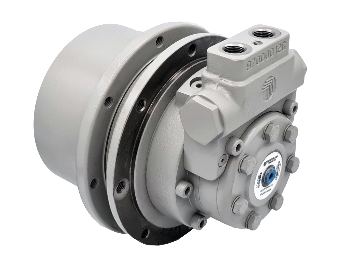
The final drive allows the transmission of hydraulic power of the machine in the form of torque directly to the drive wheels of the mobile machine. The hydraulic motor receives the flow of oil generated by the hydraulic pump, and its shaft rotates at a certain speed with its corresponding torque.
When the torque is mechanically transmitted to the reducer, it reduces the output speed and increases the torque that reaches the wheel. The ratio of speed reduction and corresponding increase in torque will depend on the transmission ratio of the reducer in its gear system.
In the final drives, the hydraulic motor is usually of the orbital or axial/radial piston type.
Do you need help selecting the optimal hydraulic motor for your new equipment? Are you looking for a hydraulic motor as spare part for your machine? We work with most brands on the market and, if the spare part you need is obsolete, we will do our best to offer you the best alternative spare part to fit in your hydraulic equipment.
Create Date: 2023-12-24 17:40:00
Update date: 2024-08-21 09:00:00


SHIPPING WORLDWIDE
Let us assist you in choosing the perfect hydraulic component for your machine or upcoming project. We offer expedited shipping to anywhere in the world through top logistics companies such as DHL Express, TNT, FedEx or UPS.