What determines a hydraulic log splitter's capacity
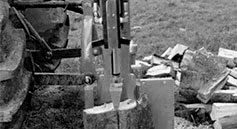
A hydraulic log splitter uses cylinder force to push wood against a splitting wedge. Required force depends on the timber species and diameter, knots, moisture, wedge condition and machine geometry. No single tonnage guarantees that every log of a given diameter can be split.
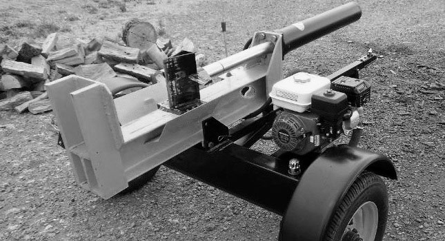
Sizing must bring together splitting force, travel speed and available power. Increasing one requirement can require changes to other components. The frame's strength and the machine's control and protective systems belong in the design from the outset.
Cylinder force and working pressure
During extension, theoretical cylinder force is F = p × A, where A is the piston bore area. At 160 bar, a 90 mm bore gives approximately 102 kN, or about 10.4 metric tonnes-force theoretically. Friction and other losses reduce the useful force.
These figures are an example, not a universal cylinder or pressure recommendation. Barrel, rod, mountings and frame must withstand the loads. Select stroke for the actual log length and machine geometry, checking stability and rod buckling where relevant.
Flow and extension time: a worked example
A cylinder with a 90 mm bore and 500 mm stroke holds approximately 3.2 litres in its extension chamber. Filling that volume in 10 seconds requires a theoretical flow of 19.2 l/min. Actual movement depends on losses and circuit conditions.
In a double-acting cylinder, the rod-side chamber has a different effective area. Retraction speed and force therefore differ from extension at the same supplied flow and pressure. Checking both movements prevents the design from being based solely on the outward stroke time.
Pump, drive and reservoir
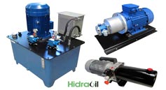
- Pump: choose displacement, speed and pressure capability from the performance curves and duty cycle. Gear pumps are common, but construction type alone does not define the permissible pressure.
- Drive: confirm that the electric motor, engine or tractor PTO can provide the required shaft power and speed.
- Reservoir: size its volume for flow, deaeration, temperature and operating duration.
A 45–60 litre reservoir for 30 l/min may be a preliminary reference from the original example. It does not replace a thermal assessment or the particular requirements of the installation.
Directional valve and system protection
The directional valve, pressure-relief valve, filters and hoses must suit the circuit. The directional valve's neutral configuration depends on the pumping arrangement and load control. A vertical cylinder position alone does not determine the correct centre condition.
These calculations help explain component selection; they are not construction drawings. Frame validation, log restraint, controls and protective measures require competent design. For a tractor-driven arrangement, see the guide to log-splitter components connected to a tractor PTO.