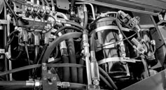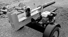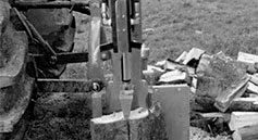
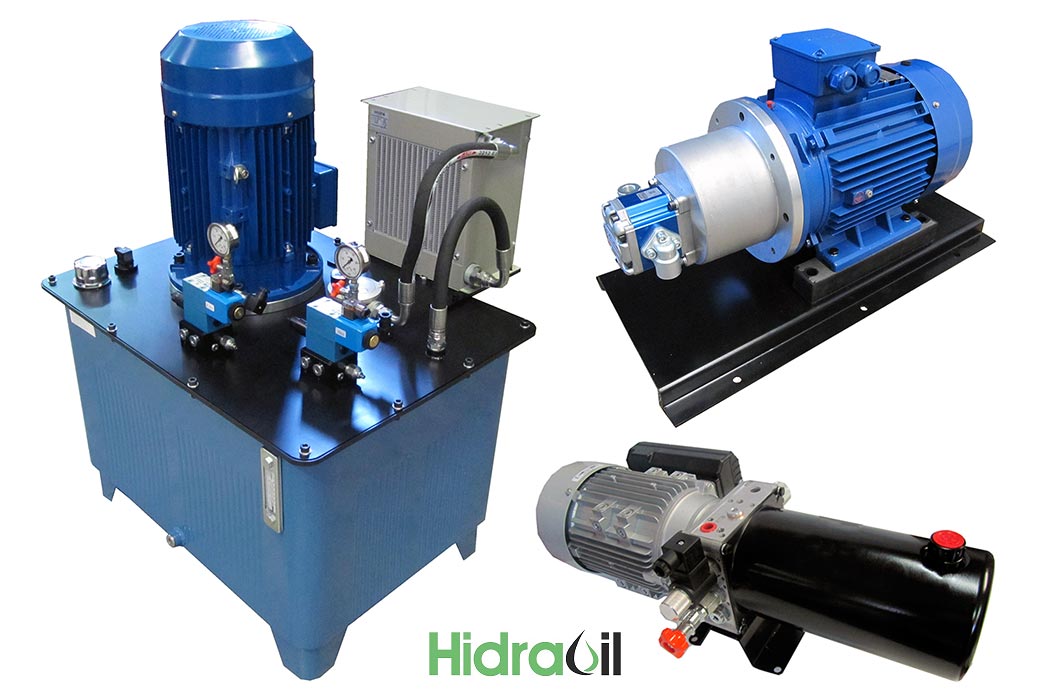
A hydraulic power unit or mini power pack supplies controlled oil flow and pressure to cylinders and motors. Its purpose is to turn drive energy into linear or rotary movement, force or torque. Motor size alone is not enough to specify the equipment: describe what the machine must do and for how long.
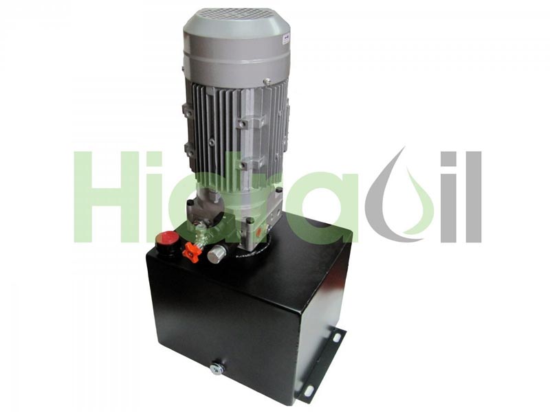
1. Flow, pressure and required power
Flow, normally expressed in litres per minute, influences actuator speed. Pressure in bar relates to available cylinder force or hydraulic motor torque. Specify the flow and pressure required simultaneously rather than combining maximum figures that never occur together.


These requirements establish drive power, operating speed and the type and displacement of the pump. Theoretical hydraulic power is Q × Δp / 600 with Q in l/min and Δp in bar; required mechanical drive power must include the relevant losses.
The hydraulic power guide and calculator explains the distinction between useful hydraulic output and required motor power.
2. Electric or combustion drive
Once demand is defined, choose the available energy source. An electric motor must match the installation's supply and duty. A petrol or diesel engine represents a different operating and energy-supply arrangement. The choice also affects mounting and the working environment.
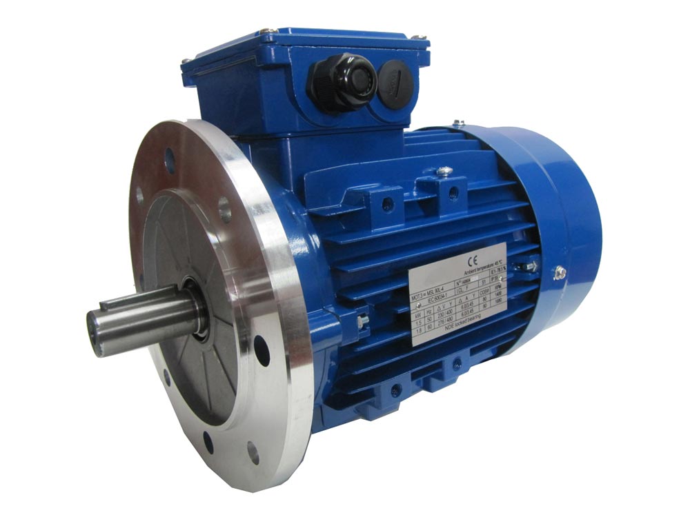
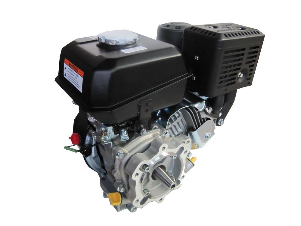
Provide speed and duty information: starts, operating time, pauses and simultaneous movements. Equipment running one minute per hour has different demands from equipment in continuous operation.
3. Reservoir volume and heat management
The reservoir must provide enough oil to fill cylinders, motors, lines and other internal volumes while allowing for level changes during movement. It also contributes to dissipating the heat generated by the system.
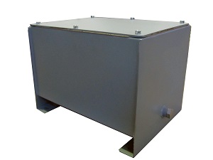
Do not select a tank solely by the available space. Required volume depends on the circuit, heat exchange and duty cycle. The aim is to maintain oil within its permitted temperature and viscosity conditions, not to cool it without limit: excessively low temperature can also be unsuitable.
4. Actuation and control configuration
Define how each movement is commanded: manually, electrically, pneumatically or by hydraulic pilot control. Also specify spool and directional-valve centre configuration: open centre, closed centre, Load Sensing (LS) or power beyond where appropriate.
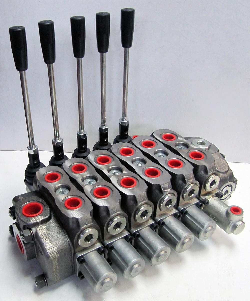
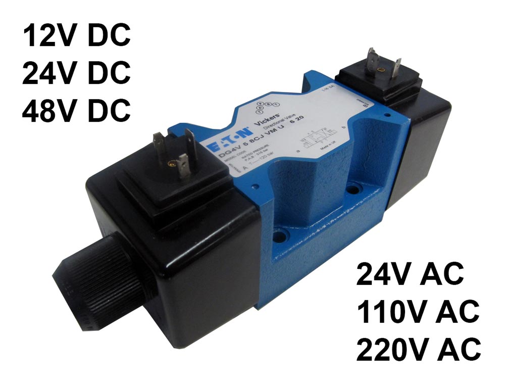
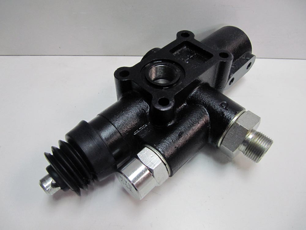
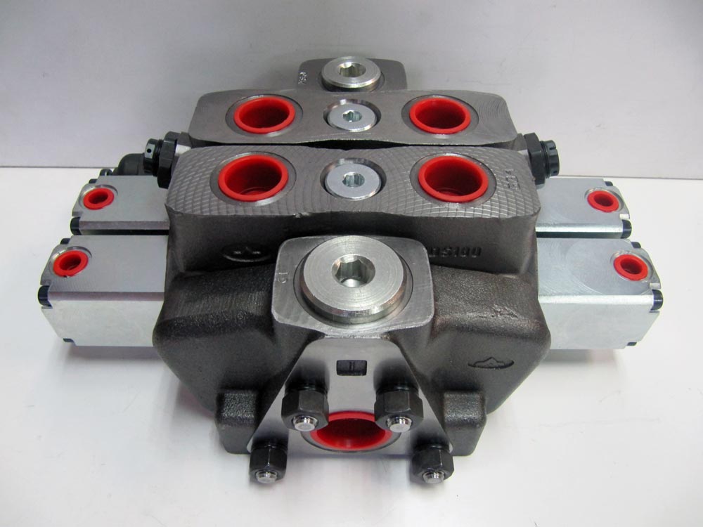
Centre configuration and control functions must suit the pump and circuit strategy. They are not interchangeable choices based only on the number of levers or coils.
5. Pressure, flow and directional valves
The circuit diagram must identify the functions needed to control motion and maintain the intended operating conditions. Common functions include:
- Pressure relief and check valves.
- Flow dividers and flow-control valves.
- Sequence and pressure-reducing valves.
- Load-control or counterbalance valves.
- Circuit-selector or diverter valves.
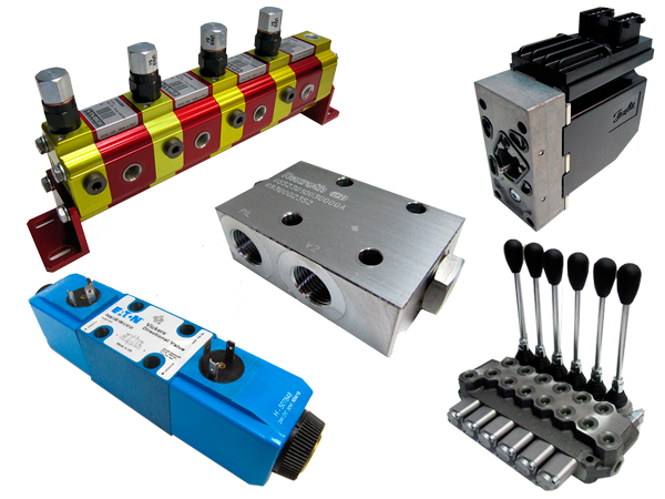
Each function needs sizing and adjustment for its actual flow and pressure conditions. Hydraulic symbols help document the diagram and communicate how the assembly is intended to work.
6. Filtration
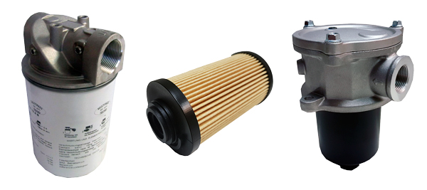
Identify the required filtration and its position: suction, return and/or pressure line. Location and filter element must suit the line's flow and operating conditions. Oil cleanliness belongs in the design, not only in subsequent maintenance.
7. Instrumentation and monitoring
Define which variables need visual indication or automatic monitoring: pressure, temperature, reservoir level and filter condition, for example. Equipment can include pressure gauges, visual or electrical level indicators, thermometers, thermostats, pressure switches and clogging indicators.
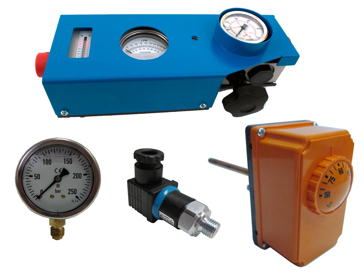
A clogging indicator reports filter condition according to its design; it does not replace a complete oil-quality assessment. Instrumentation should allow the power unit's intended operating conditions to be checked.
Information needed for selection
Provide movement descriptions, cylinder and motor data, flow, pressure, cycle timing, available supply and installation environment. Include an existing circuit diagram and references or photographs for replacements. These details support a coordinated choice of pump, drive, reservoir and controls.