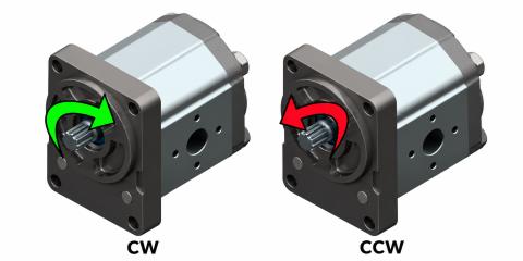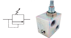
A gear flow divider distributes one pump's delivery between two or more branches. It can coordinate hydraulic cylinders or motors and, in suitable versions, combine return flows. Branch flows add up to the total flow, allowing for equipment losses.
Applications and construction
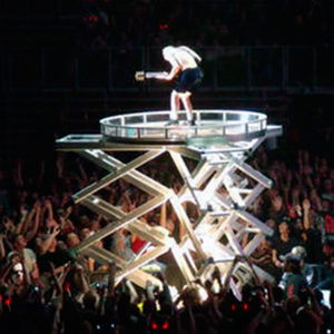
Applications include stage lifting, doors, platforms and bridges, woodworking machinery, military installations, lubrication, food-processing equipment, container handling, waste-bin lifting, sheet-metal shears and presses, and concrete mould filling and demoulding.
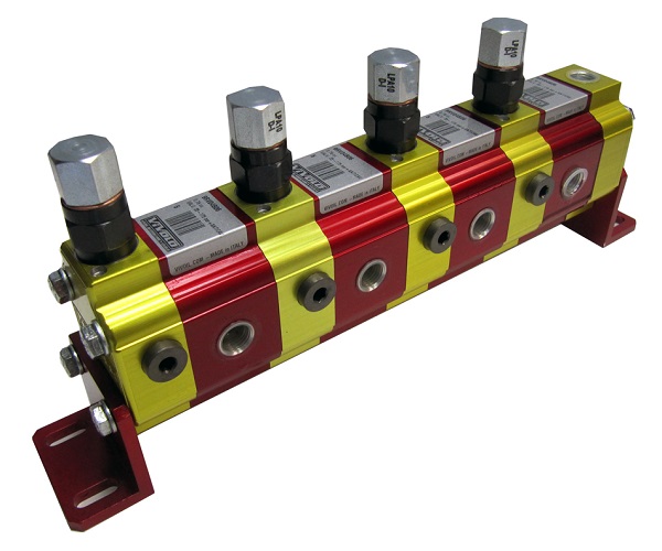
The assembly has two or more sections, each with a gear pair mechanically connected to the others. All gears turn at the same speed, driven by pressurised incoming oil in a manner comparable to a hydraulic motor. Each section's displacement determines its share of flow.
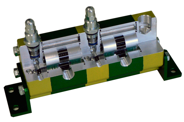
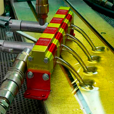
Equal sections provide approximately equal flows. This supports similar speeds in cylinders with equal effective areas or motors of equal displacement. It is not perfect synchronisation: internal leakage, load differences and phase correction affect the outcome. Compared with some throttling arrangements, gear dividers can improve energy use and reduce the number of pumps and mechanical couplings; actual benefits depend on the circuit.
Versions and phase correction
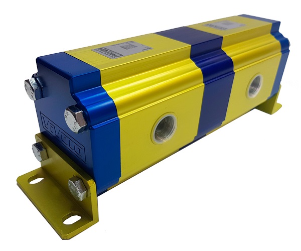
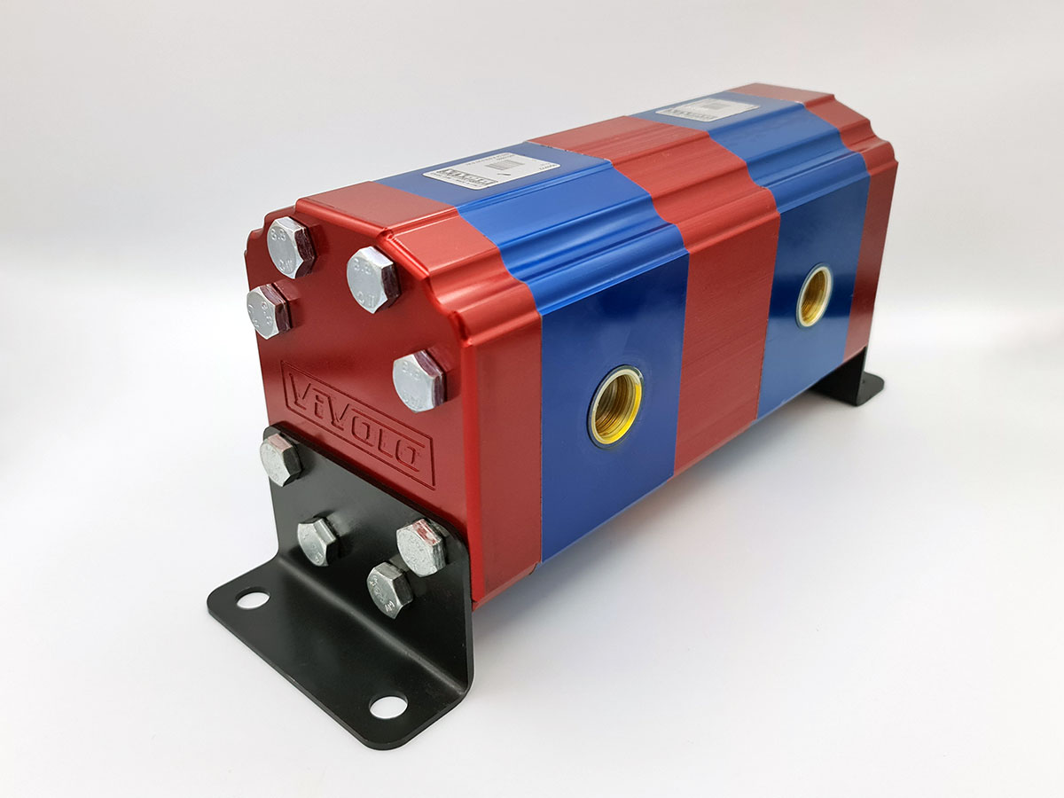
Valveless dividers
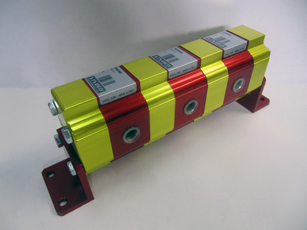
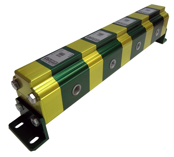
These divide and combine flow without correcting accumulated position error themselves. The following recommended per-section ranges apply to certain aluminium families; always check the exact model.
| Group | Indicative recommended section flow |
|---|---|
| 0 | 0.4–5 l/min |
| 1 | 2–20 l/min |
| 2 | 7–71 l/min |
| 3 | 27–117 l/min |
One common valve
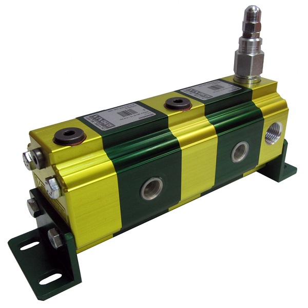
A common valve allows phase correction during division, rather than equivalent correction during combining. In the latter direction, end-of-stroke equalisation relies on internal leakage. Commissioning is simpler because only one valve is adjusted. An indicative setting is at least 15–20 bar below the main relief valve, subject to model-specific instructions.
Valves on every section
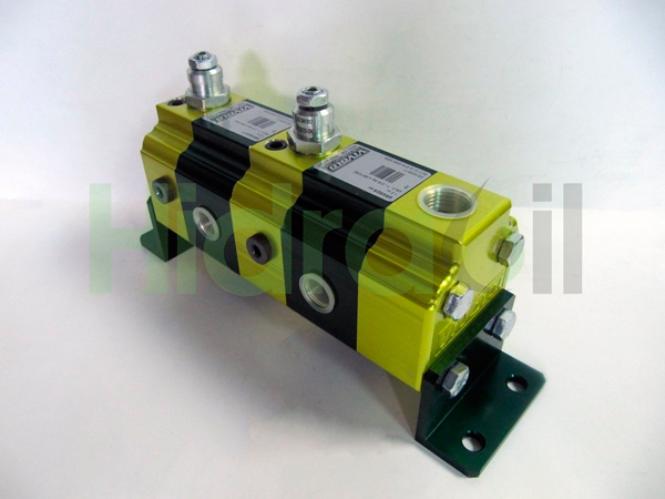
Each module includes phase-correction and anti-cavitation functions, enabling correction during division and combining. Section settings can differ. The same indicative 15–20 bar margin below the main relief valve applies, subject to the manufacturer's final adjustment procedure.
Divider with an auxiliary motor
An integrated reversible hydraulic motor helps the divider rotate when inlet or return conditions do not provide sufficient starting torque. Selection must account for the actual conditions in both directions.
Starting pressure and return flow
The divider needs sufficient pressure to start. Indicative requirements of 15–50 bar depend on model and displacement; low system relief settings, for example 40–60 bar, may also cause difficulties. These are not universal minimums: consult manufacturer data at the intended flow.
During lowering of single-acting cylinders, insufficient load may fail to generate the pressure required for combining. With double-acting cylinders, return flow can exceed pump flow according to the ratio of full piston area to rod-side annular area. Size the divider and lines for both movements.
Operating conditions and accuracy
An indicative operating speed for certain ranges is 1,600–2,200 rpm, depending on model and displacement. It also associates a section pressure difference no greater than 30 bar with accuracy within 3%, subject to manufacturer and operating conditions. This is not a rating for every divider. Each section must remain within its catalogue pressure limit.
| Parameter | Indicative reference conditions |
|---|---|
| Oil temperature | +30 to +60 °C |
| Viscosity | 20–40 cSt |
| Filtration | 10–25 µm |
| Ambient temperature | 0 to +50 °C |
| Fluid | HLP or HV mineral oil, DIN 51524 |
Appropriate check or load-holding valves belong between the divider and actuators, as close to the cylinders as practical, according to the required safety design. Placing them only upstream of the divider does not prevent cross-flow through its internal leakage paths.
Vivoil MIA-FD for unequal loads
The self-compensating MIA-FD addresses substantial load differences. Vivoil specifies accuracy within 1.5% for pressure differences up to 170 bar under its stated conditions; this must not be extrapolated beyond that range. Its interfaces accept CETOP NG6 valve modules. Consult the manufacturer's data.
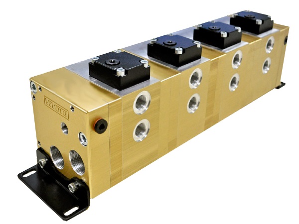
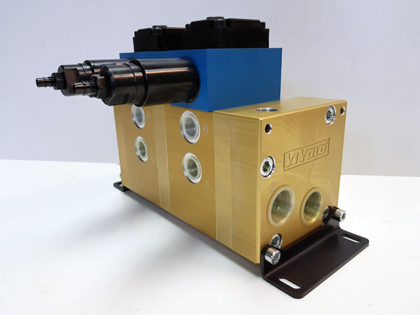
The demonstration video shows three cylinders at approximately 0, 125 and 80 bar. Over a 500 mm stroke, final differences are around 5 mm, or 1% of stroke. This is a particular demonstration, not a universal performance guarantee.
Unequal flow division: worked example
Sections can have different displacements. With 6 cm³/rev and 14 cm³/rev sections, an inlet flow of 40 l/min theoretically divides into 40 × 6/20 = 12 l/min and 40 × 14/20 = 28 l/min.
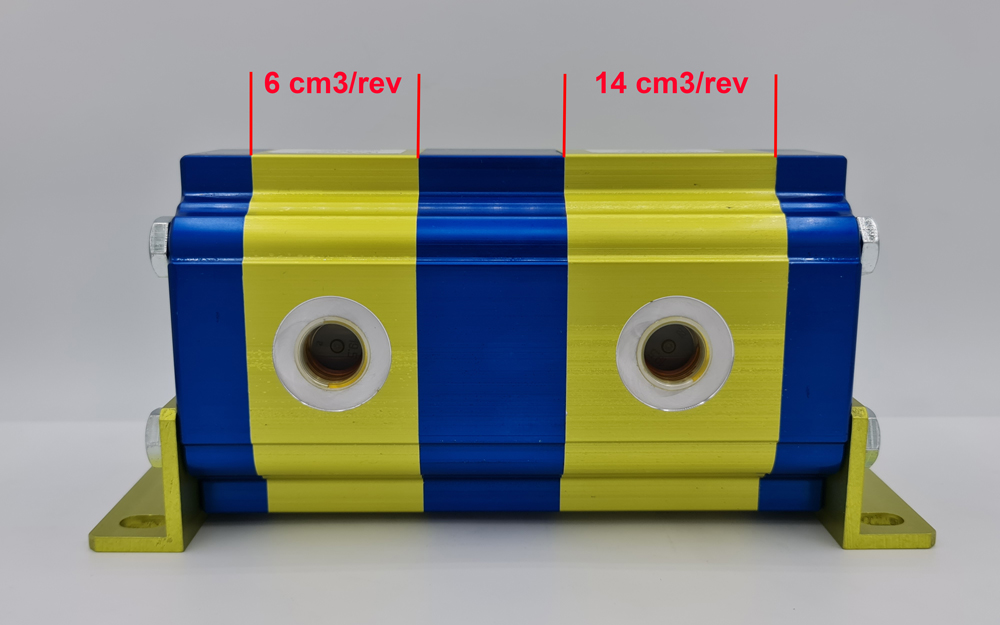
Some dividers can also intensify pressure, within the design and limits of the circuit. This function does not apply to every model: Vivoil excludes MIA-FD from pressure multiplication because of its internal compensation.
Circuit diagram and selection information
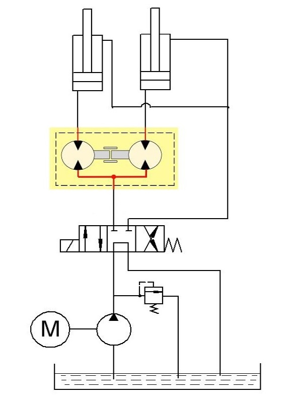
The diagram illustrates a divider supplying two double-acting cylinders. For selection, establish inlet and return flows, number and displacement of sections, cylinder areas, loads, branch pressures, required accuracy and phase-correction needs. These details support assessment of the complete installation rather than nominal divider size alone.