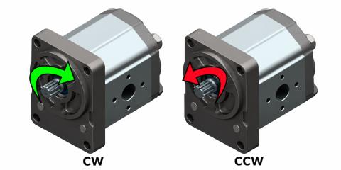
A hydraulic pressure relief valve opens a discharge path when pressure reaches the conditions defined by its setting. It limits pressure in the circuit, or in a particular section, and helps protect components against overload.
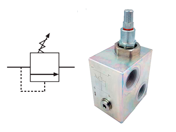
How a hydraulic pressure relief valve works
In a direct-acting valve, hydraulic pressure acts on a closing element, which may be a ball, poppet or spool depending on the design. A spring holds that element closed. When hydraulic force exceeds the closing force, the valve opens a path to divert flow, usually to the reservoir.
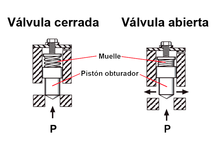
The valve begins opening at a particular pressure, but it needs sufficient pressure difference to pass the required flow. Cracking pressure and pressure at full rated flow are therefore not necessarily the same. Check the manufacturer's pressure-flow curve to assess this behaviour.
Discharged oil passes through a pressure drop, converting energy into heat. Higher diverted flow and pressure mean greater power dissipation. A relief valve protects against certain overpressure conditions, but continuous bypass can heat the oil and waste energy.
Direct-acting and pilot-operated valves
Direct-acting relief valves
Circuit pressure acts directly on the element controlling the main flow path. Construction and response vary between models. The setting may be fixed or adjustable; a direct-acting valve does not necessarily have an accessible manual adjustment.
Pilot-operated relief valves
A pilot stage controls the pressure acting on the main stage. This allows a relatively small control flow to govern the main flow path. The term “pilot-operated” does not itself mean electrical, pneumatic or remote operation: those additional functions depend on the specific configuration.
Common mounting formats
The pressure-limiting function can be integrated into different bodies and assemblies. In-line valves connect to pipework; cartridges fit into a manifold cavity; modular and subplate valves integrate with other hydraulic elements. Flange-mounted assemblies and valves designed to mount directly on hydraulic motors are also available.
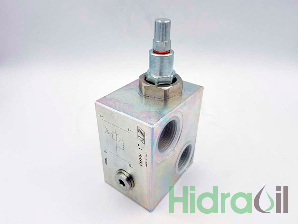
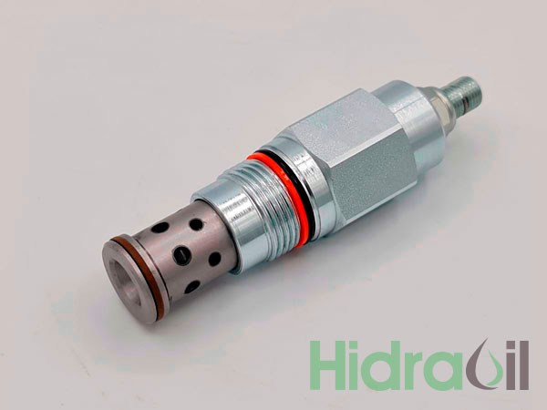
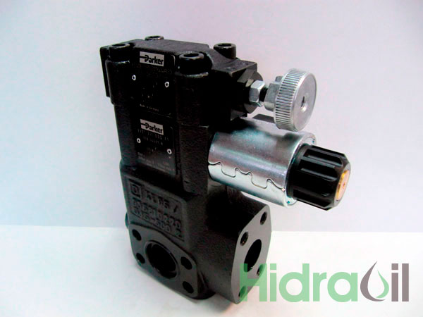
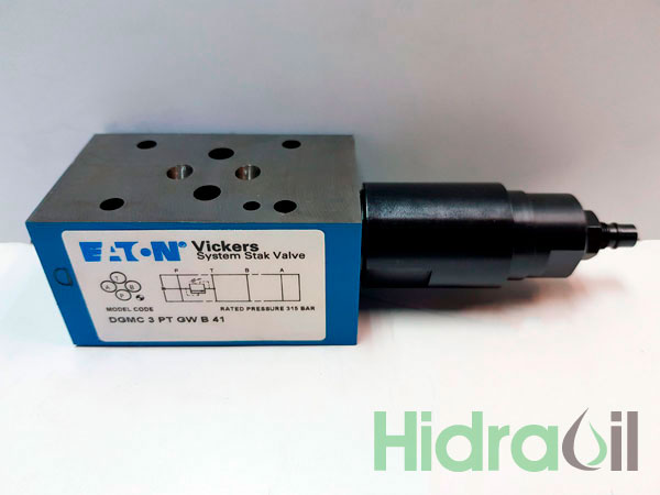
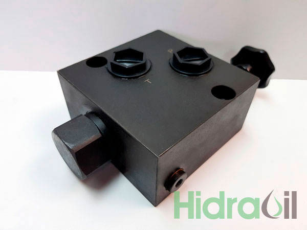
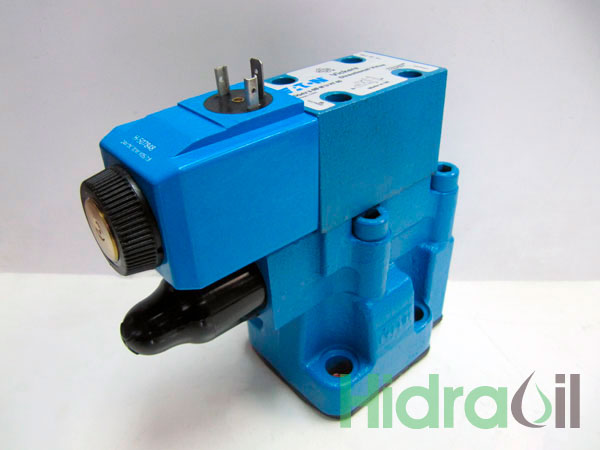
These formats are not interchangeable based on appearance. The cavity, mounting surfaces, internal passages and flow direction must match the circuit design.
Settings, spring ranges and back pressure
A valve may have a factory-set pressure or allow adjustment within an approved range. Some models use different springs for different ranges. Changing a spring still requires the approved part and procedure; spring colour is not a universal identification system.
Return-line back pressure and the drain or pilot arrangement can affect operation. Consult the manufacturer's limits. A relief valve also does not necessarily suppress every transient peak or replace the dedicated protection required for suspended loads and other machine hazards.
How to select a pressure relief valve
- Define operating pressure, adjustment range and maximum permissible pressure.
- Check the complete flow to be relieved and the pressure-flow curve.
- Verify fluid, viscosity, temperature, materials and cleanliness requirements.
- Confirm connections, mounting, permitted back pressure and dynamic response.
- Assess heat dissipation where relief operation is frequent or prolonged.
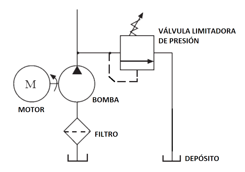
A common installation position is at the pump outlet, giving the flow a discharge path when load pressure becomes excessive. Other sections may need their own protection if they can become isolated. Qualified personnel should set and verify the valve with a pressure gauge according to the machine procedure.