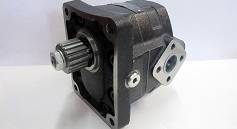
What an external gear hydraulic motor does
An external gear hydraulic motor converts the energy of pressurised oil into rotary motion. Its shaft delivers torque to drive a load. Although it may resemble a gear pump, the function and construction requirements differ: do not assume that a pump can operate as a motor without the manufacturer's approval.
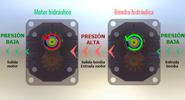
How rotation is generated
Oil enters through the higher-pressure port and acts on two meshing gears inside the housing. Fluid travels between the teeth and housing walls to the lower-pressure outlet. The pressure difference acting on the assembly generates the torque transmitted to the shaft.
Keep two quantities separate: differential pressure relates to torque, while flow rate relates to speed. Outlet pressure matters. An inlet gauge alone is not sufficient for a torque calculation when there is significant return-line backpressure.
Motor torque calculation
For displacement V in cm³/rev and pressure difference Δp in bar, available torque is estimated as M = V × Δp × ηhm / 62.8, in N·m. Here ηhm is the motor's hydromechanical efficiency at the relevant operating point.
For example, V = 20 cm³/rev, Δp = 100 bar and an assumed efficiency of 0.80 give approximately 25.5 N·m. This is an illustrative calculation, not a guaranteed rating for a particular motor. Selection must use the actual performance curves and also account for starting torque and continuous or intermittent operating conditions.
Relationship between flow and speed
Theoretical speed is n = 1000 × Q / V, with Q in l/min and n in rpm. Actual speed depends on volumetric efficiency. At the same flow, a larger-displacement motor turns more slowly and can deliver more torque at the same pressure difference, within its design limits.
Flow control can adjust speed, but the circuit must be designed for the load and resulting losses. Check the allowed minimum and maximum speeds, fluid compatibility and cooling requirements rather than treating speed regulation as an isolated adjustment.
Applications and selection checks
Typical uses include brush cutters, saws, conveyors, fans, agricultural machinery and industrial equipment. Compact construction and mounting options suit a wide range of installations when the correct configuration is chosen.
- The machine's required torque and speed.
- Displacement, available flow and pressure throughout the duty cycle.
- Unidirectional or reversible operation and case-drain requirements.
- Shaft, flange and ports, together with permitted radial and axial loads.
- Hydraulic protection, braking or mechanical support required by the load.
Use the complete part number and manufacturer's drawing when comparing a replacement. For differences between gear, orbital, vane and piston designs, see the guide to hydraulic motor types.