
How the motor drives a brush cutter
In a hydraulic blade or chain brush cutter, the motor receives oil flow and delivers rotary motion to the cutting mechanism. The speed of that mechanism depends on motor displacement, incoming flow and the fitted transmission. Some designs operate at around 1,500–2,000 rpm, but the correct speed is always the speed permitted for the machine and its cutting head.
Gear motors and rotation
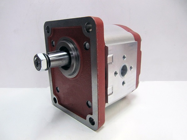
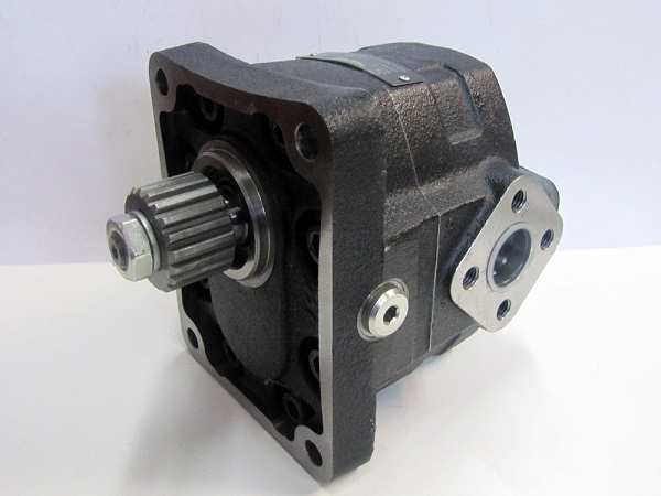
Hydraulic gear motors provide a compact option for this application. Versions are available with aluminium housings and steel or cast-iron housings. Depending on model and displacement, some ranges cover 500–4,500 rpm and pressure differentials up to 200–240 bar. These are indicative ranges across different units, not permitted operating conditions for every motor.
When reversible operation is useful
A reversible or bidirectional motor can change its direction of rotation and may help clear a blockage in equipment designed for that function. Before reversing, confirm that the cutting head, transmission and hydraulic circuit permit the manoeuvre and follow the machine’s safety procedure. A reversible motor does not make every brush cutter suitable for reverse operation. Physical intervention in a blockage requires the machine to be stopped and isolated according to its instructions.
Internal or external case drainage
Drainage depends on the motor’s construction. Externally drained models need an additional line to the reservoir. Other versions route drainage through internal cavities and valves. Check the port arrangement and permitted return and case pressures; do not choose a replacement solely because the housing or flange looks similar.
Protect the shaft with a suitable bearing support
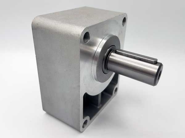
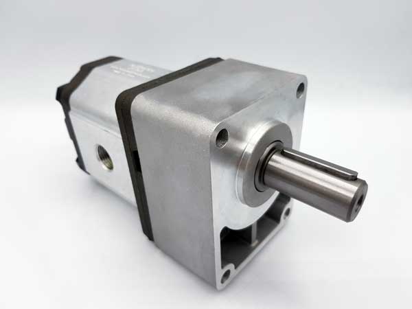
The cutting mechanism can transmit radial or axial loads that a conventional gear motor is not designed to carry directly. Use a suitably rated bearing support, pulley support or coupling, matched to the machine loads and motor capabilities. The assembly can be connected through a coupling half or sleeve. Correct alignment is as important as selecting the right displacement.
Size the motor for tractor working flow
Establish available flow at both normal working speed and the tractor’s maximum speed. For example, a tractor delivering 30 l/min at maximum engine speed may supply only 20 l/min at a less demanding working speed. The motor should achieve the required operating speed with that 20 l/min while also accepting the maximum 30 l/min without exceeding its permitted speed. Selecting it only from the maximum-flow figure can leave the machine too slow in normal operation.
Hydraulic protection and final selection
The circuit must limit overpressure and keep motor flow within its permitted range. Pressure-relief and flow-control arrangements must be selected and adjusted for the actual circuit design. Before ordering, gather the required displacement, rotation, flow, pressure, drainage, flange and shaft details, together with the bearing-support specification. Hidraoil can check these requirements against the appropriate motor reference for the application.