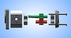
What an external gear hydraulic pump does
An external gear pump converts mechanical energy from an electric motor or engine into hydraulic energy. It supplies flow to cylinders, hydraulic motors and other actuators. Pressure develops as that flow meets the resistance of the load; it is not an independent output that the pump generates regardless of the circuit.
The compact construction, robust design and balance between cost and performance make these pumps common in agricultural, industrial and mobile machinery. Choosing one requires the actual duty conditions, rather than simply matching its appearance or body size.
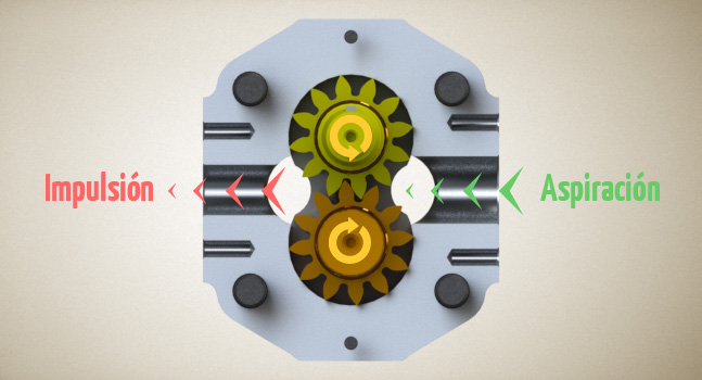
Main components and the oil path
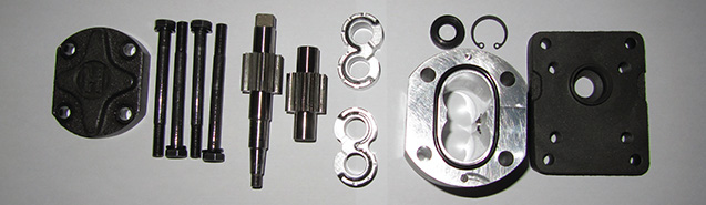
The housing contains two meshing external gears. The drive gear receives rotation from the prime mover through its shaft and turns the driven gear. The housing, covers, bearing elements and seals define the inlet and delivery regions and support the rotating assembly.
- Inlet: as the teeth disengage, the available volume increases. The pressure difference allows oil from the reservoir to fill the spaces.
- Transfer: oil travels between the gear teeth and the internal housing wall, around both sides of the gear set.
- Delivery: the teeth mesh again, reducing the cavity volume and displacing oil into the circuit.
The useful oil flow passes around the outside of the gears. The meshing region separates the two ports; it should not be understood as a passage carrying oil directly through the centre of the pump.
Displacement, speed and flow rate
Displacement is the geometric volume moved per revolution. With V in cm³/rev and shaft speed n in rpm, theoretical flow is Q = V × n / 1000, in l/min. Actual delivery is lower because of internal leakage and depends on volumetric efficiency at the operating pressure, viscosity and speed.
Higher rpm increases flow within the permitted speed range. It does not remove inlet restrictions, pressure limits or the power requirement of the drive. Use the manufacturer's performance curves rather than assuming one efficiency value applies to every gear pump.
Checks when selecting a replacement pump
- Displacement, required flow and permissible speed range.
- Working pressure and the pressure peaks expected during the cycle.
- Direction of rotation, using the viewing convention specified by the manufacturer.
- Shaft, mounting flange, ports and compatibility of the fluid and sealing materials.
- Inlet conditions, oil cleanliness and appropriate pressure-relief protection.
A visually similar pump may have a different internal configuration. Compare the complete part number and dimensional drawing before replacing it. To assess the oil supply for an application, see the guide to gear-pump displacement and flow calculations.