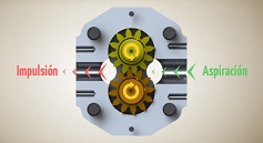
How to identify direction of rotation
The direction of rotation of a gear pump must match its drive and internal configuration. Always use the viewing convention stated in the catalogue. The usual convention is to look directly at the drive-shaft end of the pump.
- Clockwise rotation: the shaft turns clockwise when viewed from that end.
- Counterclockwise rotation: the shaft turns counterclockwise from the same viewing position.
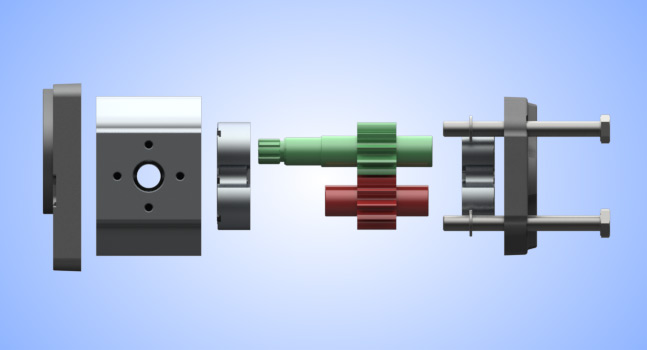
Do not compare one unit from the shaft end and another from the rear cover: the same movement appears reversed when viewed from the opposite side. Check the manufacturer's arrow or marking and the full pump identification code.
Why reversing the drive is not enough
In a unidirectional pump, the inlet and delivery ports are associated with the internal design. Depending on the model, this includes seal arrangement, internal pressure compensation and shaft-seal protection. Driving it in the opposite direction may prevent correct operation or damage the unit. Swapping the hoses alone does not turn a unidirectional pump into a reversible one.
Check whether conversion is permitted for the exact pump series. If the manufacturer does not provide for it, select a unit with the correct rotation. A reversible pump is a specifically rated configuration, not simply a pump with similar-looking ports.
What the dismantling illustrations show
The following pictures illustrate one particular pump configuration. They help identify the components involved but are not a universal conversion procedure for every external gear pump.
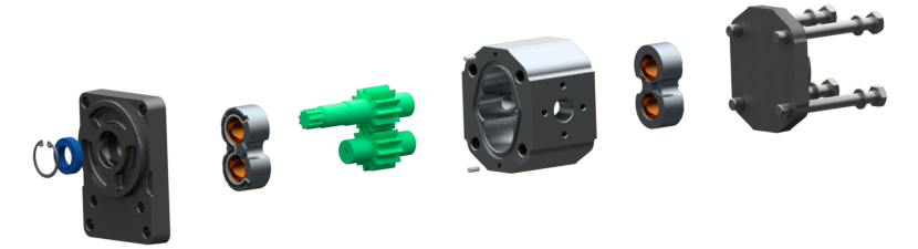
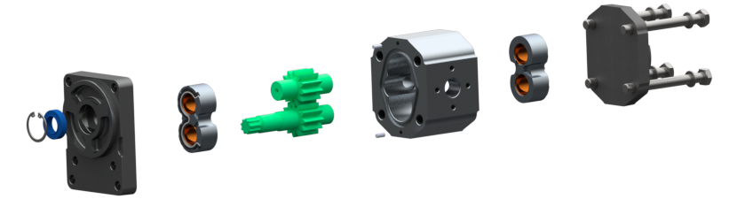
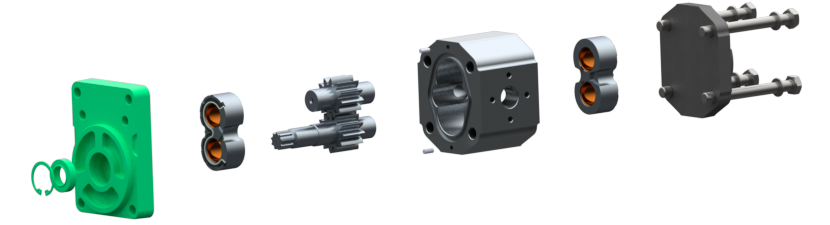
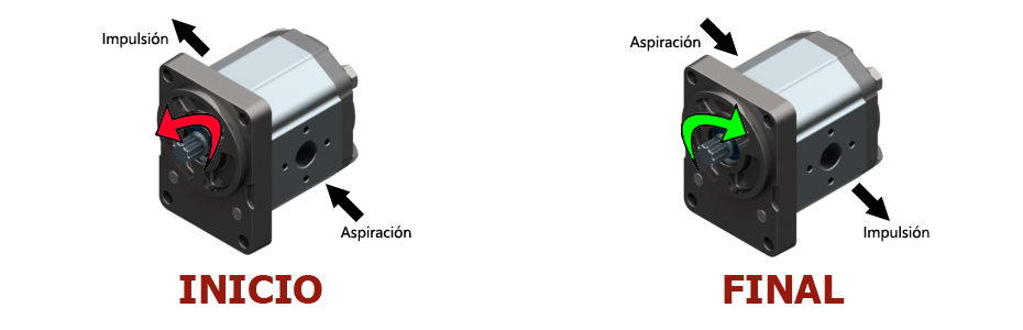
The repositioning of gears, plates, seals or flanges, tightening torques and subsequent checks depend on the manufacturer. An explanation valid for one unit must not be applied to another simply because their housings look alike.
Checks before conversion
- Pump part number, series and revision, together with the machine's required rotation.
- Approved conversion instructions and any seals or parts that must be replaced.
- Final identification of inlet and delivery ports and connection compatibility.
- Condition and cleanliness of the components, coupling installation and commissioning requirements.
Qualified personnel should perform the work with the machine isolated and hydraulic pressure released. When selecting a replacement, compare shaft, flange, displacement and pressure rating as well. The guide to external gear pump operation explains the oil path.