A hydraulic accumulator stores energy so that oil can be returned to the circuit when pressure conditions require it. It can provide an energy reserve, compensate for small losses and pressure variations, or reduce certain shocks and vibrations. Its usefulness depends on choosing a type, volume and gas precharge suited to the application.
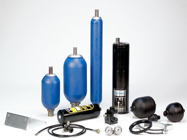
How a hydropneumatic accumulator works
A compressed gas, usually nitrogen, is separated from the oil by a diaphragm, bladder or piston. Incoming oil compresses the gas and stores energy. When circuit pressure falls, the gas expands and displaces some of the stored oil back into the installation.
Available energy depends on more than nominal vessel volume. Gas precharge, minimum and maximum working pressures and operating conditions also matter. Increasing accumulator size does not replace correct precharge selection.
Functions within a hydraulic circuit
- Energy reserve: provide flow in addition to pump delivery during a short demand peak. Correct sizing can allow a smaller motor-pump unit.
- Internal leakage compensation: replenish small losses through components such as spool valves, reducing repeated starts to restore pressure.
- Pressure variation compensation: accommodate certain changes associated with temperature and fluid volume, particularly on equipment exposed to ambient conditions.
- Shock and noise attenuation: reduce particular transients, shocks or vibrations when the accumulator response matches the application.
- Mobile machinery suspension: absorb some of the impact from uneven ground and improve load behaviour.
These benefits depend on circuit design and sizing. They are not a guarantee of energy savings or vibration elimination on every machine.
Main accumulator types
Diaphragm accumulators
Compact and lightweight, these are frequently used for smaller volumes and flows and for shock absorption on mobile machines. An indicative pressure ratio is 8:1. Actual limits depend on construction, and some models allow different ratios. Permitted mounting positions must also be checked in the catalogue.
Welded versions are generally not repaired by replacing the diaphragm; certain screw-type designs allow diaphragm replacement. Opening or dismantling requires the correct procedure and qualifications.
Bladder accumulators
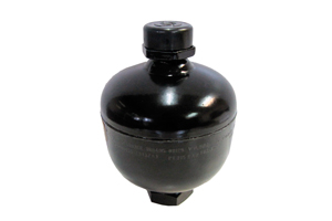
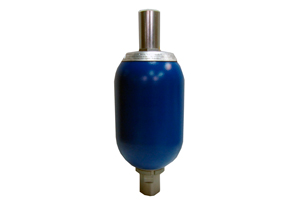
Bladder designs serve both mobile and industrial applications. Typical reference conditions are a pressure ratio of 4:1 and preferably vertical mounting, both subject to the actual model's requirements. Their relative cost is generally intermediate between the diaphragm and piston solutions of comparable specification.
Piston accumulators
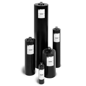
These can meet large-volume and high-flow requirements. They generally have higher relative weight and cost, with vertical mounting preferred where specified. Dynamic response depends on piston characteristics and construction. For rapid pulsation damping, assess response characteristics rather than stored volume alone.
Forklift truck applications
An accumulator selected for the lift circuit can reduce vibration transmitted to the forks and load. Without damping, vibration can impair control, increase operator fatigue and cause load or component damage. A suitable installation can improve control and comfort and reduce maintenance requirements.
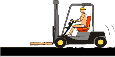
The table suggests indicative volumes by load capacity. Load mass alone does not size an accumulator: working pressures, lift cylinder, precharge and machine conditions require confirmation with the manufacturer.
| Reference load capacity | Indicative volume |
|---|---|
| 500–1,000 kg | 0.5 l |
| 1,000–3,000 kg | 0.75 l |
| 3,000–5,000 kg | 1 l |
| 5,000–12,000 kg | 2.5–3.0 l |
In the example, the accumulator connects to the line between the lift cylinder and control valve. Connections and isolation and discharge devices must follow the forklift's safety design; this description does not authorise an unvalidated modification.
Selection data, precharge and safety
Specify the intended function, pressure range, usable oil volume or flow requirement, fluid, temperature and mounting position. For replacement, identify manufacturer and reference. Units from Hydro Leduc, Fox, Bosch Rexroth, Olaer, Parker, Hydac, Integral Hydraulics, Roth Hydraulics or Saip, among others, can have different specifications.
Accumulators may be supplied with or without gas precharge. Precharge must suit the application and be checked by qualified personnel using the manufacturer's procedure. Use the specified gas, normally nitrogen; never substitute oxygen or compressed air. Before intervention, isolate the accumulator and correctly discharge its hydraulic side: stopping the pump does not remove stored energy.
Pressurised gas affects shipping arrangements, particularly air transport. Confirm supply condition, packaging and carrier acceptance with the manufacturer and transporter before dispatch. Restrictions cannot be inferred from accumulator size alone.