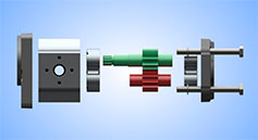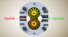
What cavitation means
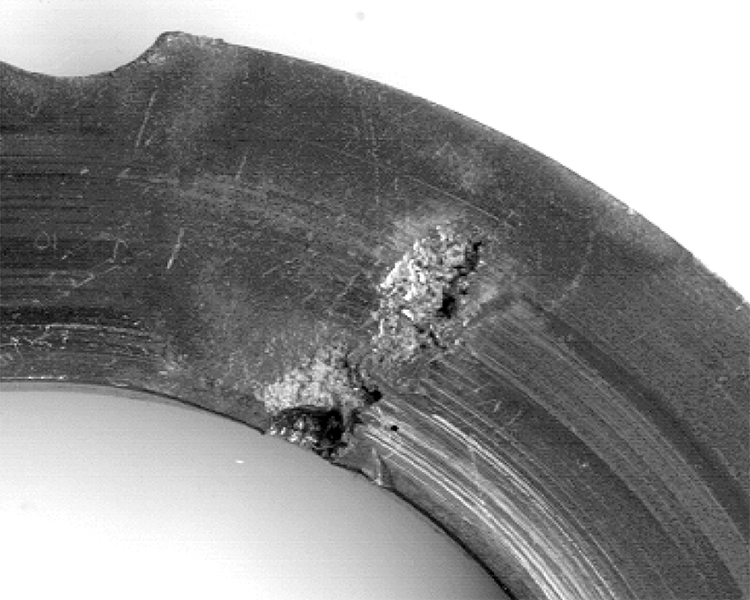
Cavitation occurs when local liquid pressure falls far enough for vapour cavities to form. When those cavities reach a higher-pressure region, they collapse and can erode internal pump surfaces. In hydraulic systems, inlet supply conditions are crucial: the pump must receive enough oil to fill its working volumes throughout its operating range.
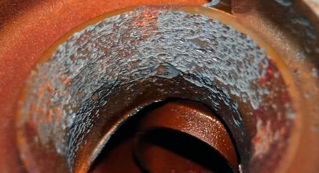
Cavitation and aeration are different
Air entering through a suction connection, or air carried in the oil, can also cause foaming, noise and irregular operation. This is aeration and should not automatically be called cavitation, although the two conditions can coexist. Not all erosion should be attributed to the so-called diesel effect either. Noise and oil appearance are useful diagnostic clues, but neither identifies the cause on its own.
Causes worth checking
Inlet restrictions are a significant cause: incorrectly sized pipes, long suction lines, excessive bends, sudden changes in section and blocked filters hinder pump filling. Low oil level, reservoir ventilation problems and shaft speeds outside the permitted range can also contribute. During a cold start, viscosity can be too high, increasing resistance to oil flow; this should not be confused with excessively low viscosity at high temperature.
Typical damage and symptoms
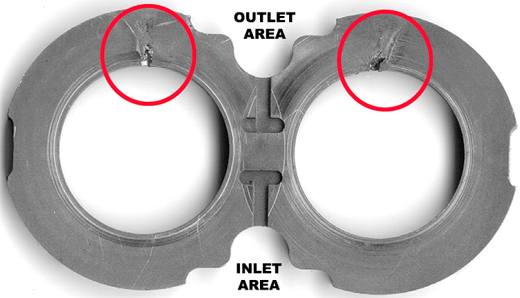
Erosion can create cavities in plates and other critical surfaces, increase internal leakage and reduce pump performance. The system may show vibration, knocking noise and erratic cylinder or motor movement. Aerated oil can look cloudy or foamy, while fluid and temperature problems can worsen wear in other components. Do not wait for visible damage before investigating abnormal noise or poor inlet supply.
Measure pressure at the pump inlet
Check inlet pressure with a suitable instrument and compare it with the manufacturer’s limits during start-up and under actual operating conditions. Distinguish absolute from gauge pressure: at an atmospheric pressure of approximately 1 bar, 0.8 bar absolute corresponds to about 0.2 bar of vacuum relative to atmosphere. This example is not a universal operating limit; the permitted value depends on the pump, fluid, speed and installation conditions.
Size and maintain the suction line
Keep the suction line as short and direct as possible and choose its bore for the expected flow and viscosity. A preliminary sizing reference is an inlet velocity of 0.5–1.6 m/s, which must be checked against the equipment documentation and resulting pressure losses. Check filter cleanliness and capacity, where a suction filter is fitted, and observe the pump’s minimum and maximum speeds. Separate the reservoir suction point from return and drain discharges to encourage air separation.
Cold starts and positive inlet supply
Use the correct oil and specified warm-up procedure to avoid poor inlet supply caused by excessive viscosity. Positioning the pump below the reservoir oil level can help supply it, provided permitted inlet pressure is respected. A pressurised reservoir or auxiliary charge pump is a design solution requiring specific sizing and regulation, not an improvised modification. In closed circuits, the charge circuit must replace losses to keep the main circuit properly supplied.
Diagnose before replacing the pump
If the problem develops, check oil supply and circuit conditions first so that a replacement pump is not exposed to the same failure. Follow the machine’s shutdown and intervention procedure and obtain technical diagnosis when needed. As a supplementary reference, the Parker Denison vane pump and motor troubleshooting guide explains the relationship between viscosity, aeration, restrictions and supply problems. The specific unit manual remains the reference for its operating limits.