How the system works
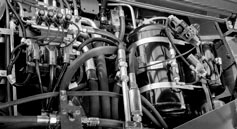
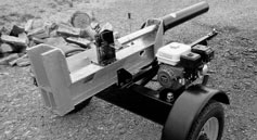
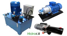
A hydraulic system converts mechanical drive energy into fluid energy and then into useful movement. The pump supplies flow, valves direct and regulate the circuit, and cylinders or hydraulic motors turn that energy into linear motion or rotation. The reservoir, filters and cooling equipment help maintain suitable oil conditions. Selection must consider the complete system and the actual machine duty cycle, rather than a collection of unrelated components.
Hydraulic pumps: choosing the technology
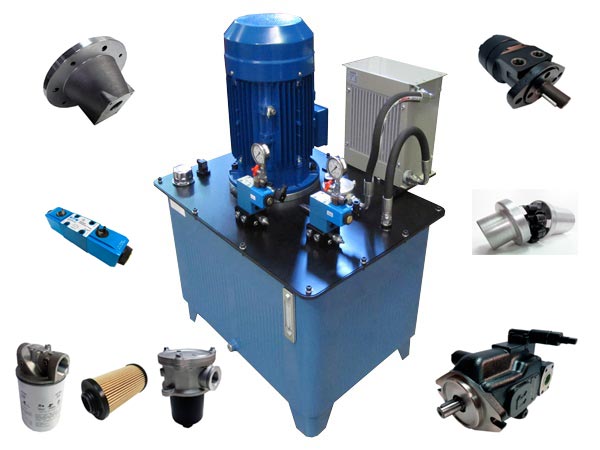
Select the hydraulic pump for flow, pressure, speed, duty cycle, temperature and fluid. Options include external and internal gear, vane and piston pumps, with fixed or variable displacement depending on the construction. Single, double or tandem, triple and multiple-section pumps are available. Displacement is the geometric volume moved per revolution; effective flow also depends on speed and volumetric efficiency.
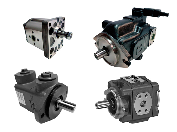
External gear pumps: connections and variants
Compact size, versatility and relatively low cost explain their use in mobile machinery and stationary equipment. Compare displacement and clockwise, anticlockwise or reversible rotation, confirming the manufacturer’s viewing convention. Check tapered, splined, cylindrical or tang shafts; European, Bosch, SAE-A/B/C, DIN or ISO flanges; and threaded, SAE, Bosch or Plessey ports. NBR, FKM or PTFE seals and integrated flow, priority, pressure or unloading valves must suit the fluid and service conditions.
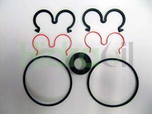
Aluminium and steel or cast-iron housings
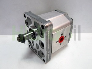
Aluminium gear pumps are used on tractors, light machinery and small or medium hydraulic power packs. Steel or cast-iron versions are chosen where the duty requires a more robust construction. Housing material alone does not establish pressure capability or suitability: compare the exact model’s catalogue limits with the machine’s operating conditions.
Internal gear pumps
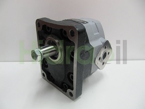
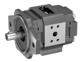
Internal gear pumps are used where low noise and pulsation and good volumetric efficiency are important. Load distribution and bearing arrangements form part of each manufacturer’s design. Multiple-pump configurations are also available. Base the selection on performance curves and the operating point, not only on a general comparison between technologies.
Vane pumps
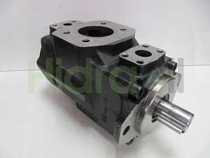
Vane pumps are available with fixed or variable displacement and are often selected for their noise and operating characteristics. Fluid and system cleanliness remain essential: oil, filters, reservoir and pipework must be maintained to the pump’s requirements. Noise or efficiency advantages do not compensate for poor inlet supply or contamination beyond the model’s permitted level.
Piston pumps
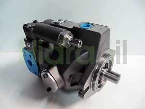
Piston pumps can be axial or radial, fixed or variable displacement, and intended for open or closed circuits. Hydrostatic transmissions require the pump to be selected together with the motor and the circuit’s charge and control functions. Pumps of different technologies or circuit arrangements should not be interchanged merely because their displacement is similar.
Electric motor and drive power
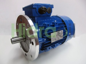
The electric motor must provide enough drive power for the required flow and operating pressure, allowing for losses and component efficiencies. Check single- or three-phase supply, 50 or 60 Hz frequency, voltage and star or delta connection where applicable. Equipment can use supplies such as 220, 400 or 600 V and 12, 24 or 48 V DC drives. Verify poles, speed, efficiency class and foot-mounted or B5/B14 flange arrangements for the selected reference.
Other drives: combustion engine and PTO
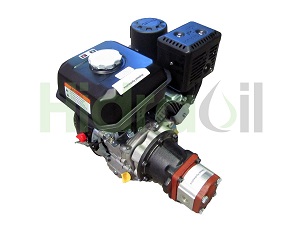
A pump may also be driven by a petrol or diesel engine, tractor or truck power take-off, or belt and gear transmission. The actual speed and available power must match the pump. Check rotation, mounting and any loads that the drive arrangement can impose on the shaft.
Bell housings and couplings
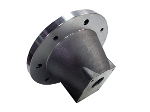
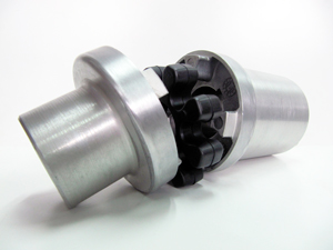
A bell housing mechanically connects the motor flange to the pump flange and locates the assembly. The coupling transmits torque between the shafts. Flexible couplings generally use two hubs and an intermediate element that tolerates small misalignment within defined limits; they do not correct a badly aligned installation. Select by torque, power, speed, shaft geometry and the manufacturer’s axial and radial alignment tolerances.
Hydraulic cylinders
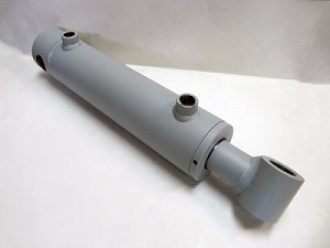
Cylinders convert hydraulic energy into linear movement. Select them by force, stroke, speed, pressure and mounting conditions. Single-acting, double-acting and telescopic cylinders are available with different mounting arrangements. Rod diameter and effective areas affect extension and retraction behaviour. The relationship between cylinder and pump sizing helps establish the required flows.
Hydraulic motors: speed and torque
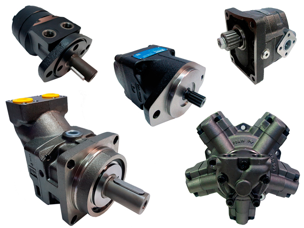
A hydraulic motor produces rotary movement from flow and pressure differential. Required speed and torque guide the choice of gear, orbital, vane or piston construction. Check rotation, internal or external drainage, ports and permitted shaft loading. Flow control and pressure limitation must keep the motor within its approved operating envelope.
Gear and orbital motors
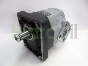
Gear motors are used in equipment requiring relatively high shaft speed, including seeders, brush cutters and fans. Orbital motors provide high torque at low or medium speeds in applications such as winches, agricultural equipment and industrial machinery. An orbital motor’s bearings may accept some shaft loading, but the catalogue values must be checked. Use external bearing support where required to protect the shaft.
Vane and piston motors
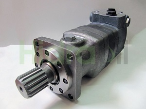
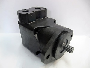
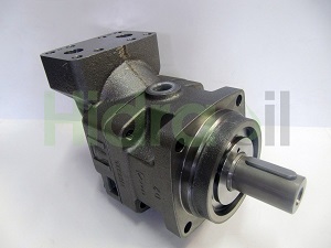
Vane motors are used, among other duties, in harvesting vibration equipment. Piston motors can be fixed or variable displacement, axial or radial, and suitable for open or closed circuits. Radial designs are often selected for high torque at low speed; axial models cover other speed requirements. Specialised models can exceed 12,000 rpm, but this capability does not apply to all piston motors.
Valves, directional controls and regulating devices
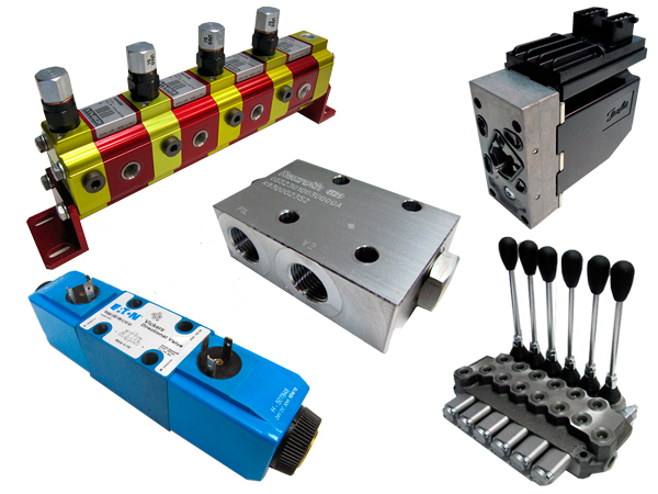
These components control oil direction, flow or pressure. Options include monoblock or sectional directional valves, flow dividers, check and sequence valves, flow controls, pressure-relief and pressure-reducing valves, and load-control or overcentre valves. Spool configuration and the centre position determine which ports are open or blocked during each operation.
In-line, flange-mounted and cartridge valves
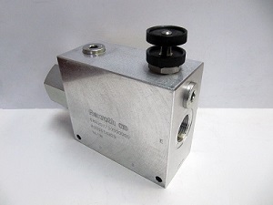
In-line valves are fitted within the pipework. Flange-mounted valves sit directly beside a pump, motor or other component, reducing external connections. Cartridge valves are inserted into machined cavities in a manifold. These arrangements can provide compact circuits, but their interfaces, internal passages, threads and mounting requirements must match the exact part.
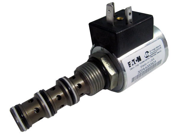
Solenoid valves and interface sizes
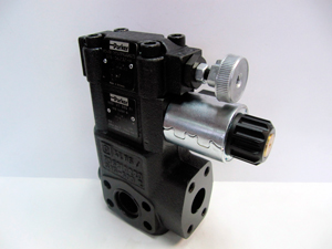
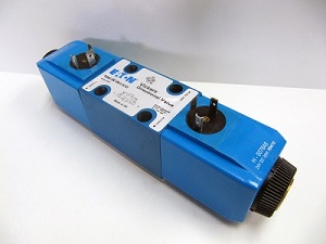
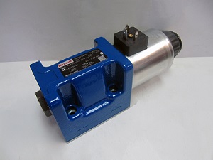
Solenoid valves use coils to actuate the hydraulic function. Check voltage and current type: versions include 12, 24 or 48 V, 105–115 V and 220–240 V, among others. Flow and mounting interface guide the size; common designations include NG4/CETOP 2, NG6/CETOP 3, NG10/CETOP 5 and NG16/CETOP 7. Always verify the mounting drawing and spool function: matching nominal size does not make two valves equivalent.
Hydraulic accumulators
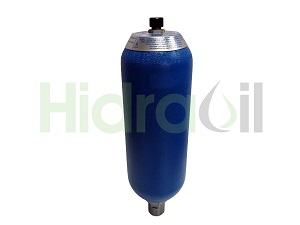
An accumulator stores hydraulic energy and returns pressurised oil when the application requires it. Bladder, diaphragm and piston accumulators are available. Select volume, pressure and configuration for the intended function and manufacturer’s requirements. Stored energy can remain after the drive stops, so maintenance must follow the equipment’s specific procedure.
Reservoir and accessories
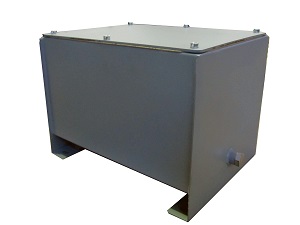
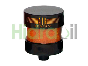
The reservoir must support oil storage, air separation and temperature control. Sizing depends on flow, pressure, ambient temperature, duty cycle and heat dissipation, as well as available space. Reservoirs can be made from steel, plastic or stainless steel. Accessories include filtered filling and breathing arrangements, a bottom drain, visual or electrical level indicators and desiccant breathers to limit incoming dirt and moisture.
Oil coolers and heat exchangers
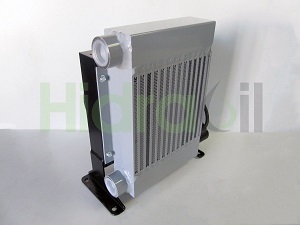
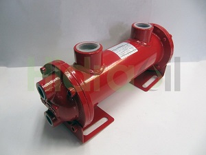
Cooling may use air, through natural convection or forced ventilation, or water. An air-cooler fan can be electrically or hydraulically driven. Marine applications need materials and arrangements suited to the environment and the cooling water. Size the heat exchanger for maximum ambient temperature, heat generated by system losses and permitted oil temperature, rather than reservoir size alone.
Oil filtration and reservoir air filtration
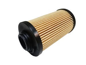
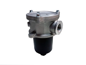
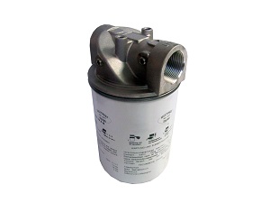
Suction filters may be submerged or external in-line units; they must protect the pump without unduly restricting supply. Return filters can be in-line or tank-top mounted. Pressure filters protect components with demanding cleanliness requirements, such as proportional or servo valves. Desiccant breathers filter air entering the reservoir, retaining particles and moisture; they do not replace oil filtration. Select capacity, filtration rating and condition indicators for the actual circuit.
Instrumentation: measure before diagnosing
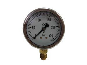
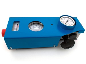
Pressure gauges and transducers, vacuum gauges, flow meters and fluid-condition indicators allow system operation to be checked. Each instrument needs the correct range, connection and operating conditions for its measuring point. Comparing pressure, flow and temperature under known conditions provides more useful information than judging one component by appearance or isolated noise.
Pressure and temperature switches
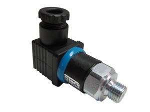
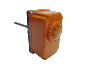
A pressure switch opens or closes an electrical circuit in response to sensed pressure. A temperature switch performs the corresponding switching function in response to temperature. They may participate in machine control or monitoring, but must be selected for the intended circuit and functions. Their settings and connections do not replace the complete protection arrangements required by the hydraulic system.
Select the components as a system
Before requesting parts, establish pressure, flow, power, speeds, duty cycle, fluid, temperature and mounting data. Check the interfaces between pump, drive, actuators and valves, together with cooling, filtration and instrumentation. Coordinated selection avoids incompatibility and unnecessary losses. Hidraoil can help match hydraulic system components to the application’s actual requirements.